
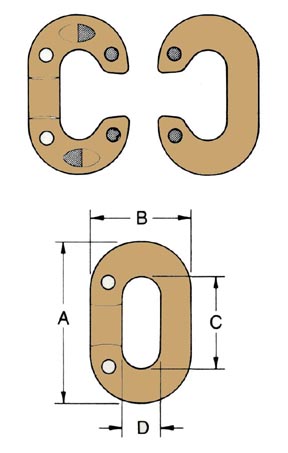
THE “CONNECTING LINK” DROP FORGED STEEL-HEAT TREATED
| Chain Size Inches | Dimensions in Inches A | Dimensions in Inches B | Dimensions in Inches C | Dimensions in Inches D | Working Load Limit Lbs. | Avg. WT. Lbs. Per 100 |
|---|---|---|---|---|---|---|
| 3/16 | 1-3/16 | 25/32 | 11/16 | 11/32 | 800 | 3 |
| 1/4 | 1-1/2 | 1 | 7/8 | 7/16 | 1,400 | 6 |
| 5/16 | 2-11/16 | 1-5/32 | 15/16 | 15/32 | 2,000 | 11 |
| 3/8 | 2-1/16 | 1-3/8 | 1-1/8 | 9/16 | 2,800 | 18 |
| 7/16 | 2-11/32 | 1-17/32 | 1-9/32 | 19/32 | 3,600 | 29 |
| 1/2 | 2-21/32 | 1-23/32 | 1-15/32 | 21/32 | 4,700 | 39 |
| 9/16 | 3 | 1-5/16 | 1-5/8 | 1/4 | 5,500 | 50 |
| 5/8 | 3-5/16 | 2-3/32 | 1-11/16 | 25/32 | 7,000 | 75 |
| 3/4 | 3-7/8 | 2-1/2 | 2-1/8 | 15/16 | 10,000 | 116 |
| 7/8 | 4-1/2 | 2-15/16 | 2-1/2 | 1-1/8 | 12,000 | 174 |
| 1 | 5 | 3-5/16 | 2-3/4 | 1-1/4 | 15,500 | 240 |
| 1-1/8 | 5-5/8 | 3-11/16 | 3-1/8 | 1-5/8 | 19,500 | 340 |
| 1-1/8 | 5-5/8 | 3-11/16 | 3-1/8 | 1-5/8 | 19,500 | 340 |
| 1-1/4 | 6-1/8 | 4-3/16 | 3-1/4 | 1-3/4 | 24,000 | 470 |
| 1-3/8 | 6-3/4 | 4-9/16 | 3-1/2 | 1-3/4 | 28,000 | 620 |
To attach, separate the halves of the “Connecting Link” which have been matched under pressure at the factory to insure a tight fit. Insert each half through the links which are to be joined together. Fit the rivets into the holes. Then een over the rivets, filling the countersunk holes. Galvanized or Self-Colored
*CAUTION: The Working Load Limit should not be exceeded.
To Be Used With Proof Coil Chain Only.
APPLICATIONS: Not for Overhead Lifting.
DESCRIPTION: All sizes have rivet holes countersunk.
Sizes 3/16″, 1/4″ and 5/16″ have rivets only.
Sizes 3/8″ and up also have interlocking lugs.
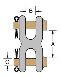
DOUBLE CLEVIS MID-LINK
| Chain Size Inches | Dimensions in Inches A | Dimensions in Inches B | Dimensions in Inches C | Working Load Limit Lbs. | Avg. WT. Lbs. Per 100 |
|---|---|---|---|---|---|
| 1/4 & 5/16 | 1-3/16 | 7/16 | 3/8 | 4,700 | 33 |
| 3/8 | 1-3/8 | 1/2 | 7/16 | 6,600 | 46 |
| 7/16 & 1/2 | 1-3/4 | 5/8 | 9/16 | 11,300 | 110 |
| 5/8 | 1-5/16 | 3/4 | 11/16 | 18,000 | 160 |
*CAUTION: This working load limit should not be exceeded.
APPLICATIONS: Used as a temporary or permanent link with proof coil or high test chain. Not to be used in Overhead Lifting.
DESCRIPTION: Drop forged, heat-treated, carbon steel, zinc-plated.